Heavy-Duty I-Beam Conveyor Systems
I-beam overhead conveyor systems for rugged, fixed-route material flow. Explore trolley chain, support steel, installation, retrofit, and service from IMH.
I-beam conveyor · Chain, trolleys, and load attachments
Choose around the work you need to move.
Plan the route and support steel together.
Bring installation into the first plan.
Your project / Next step
Review your I-beam conveyor application
Bring the load, route and operating conditions. For a modification, share the existing track and equipment information along with the proposed change.
Compare overhead conveyor arrangementsUseful details for the first conversation
- Load, fixture and trolley arrangement
- Route, elevation changes and operating environment
- Existing equipment, plant location and timing
Share what you know. Leave unknown details open.
Email IMH salesThe details shape the system.
An open track for chain-driven overhead movement.
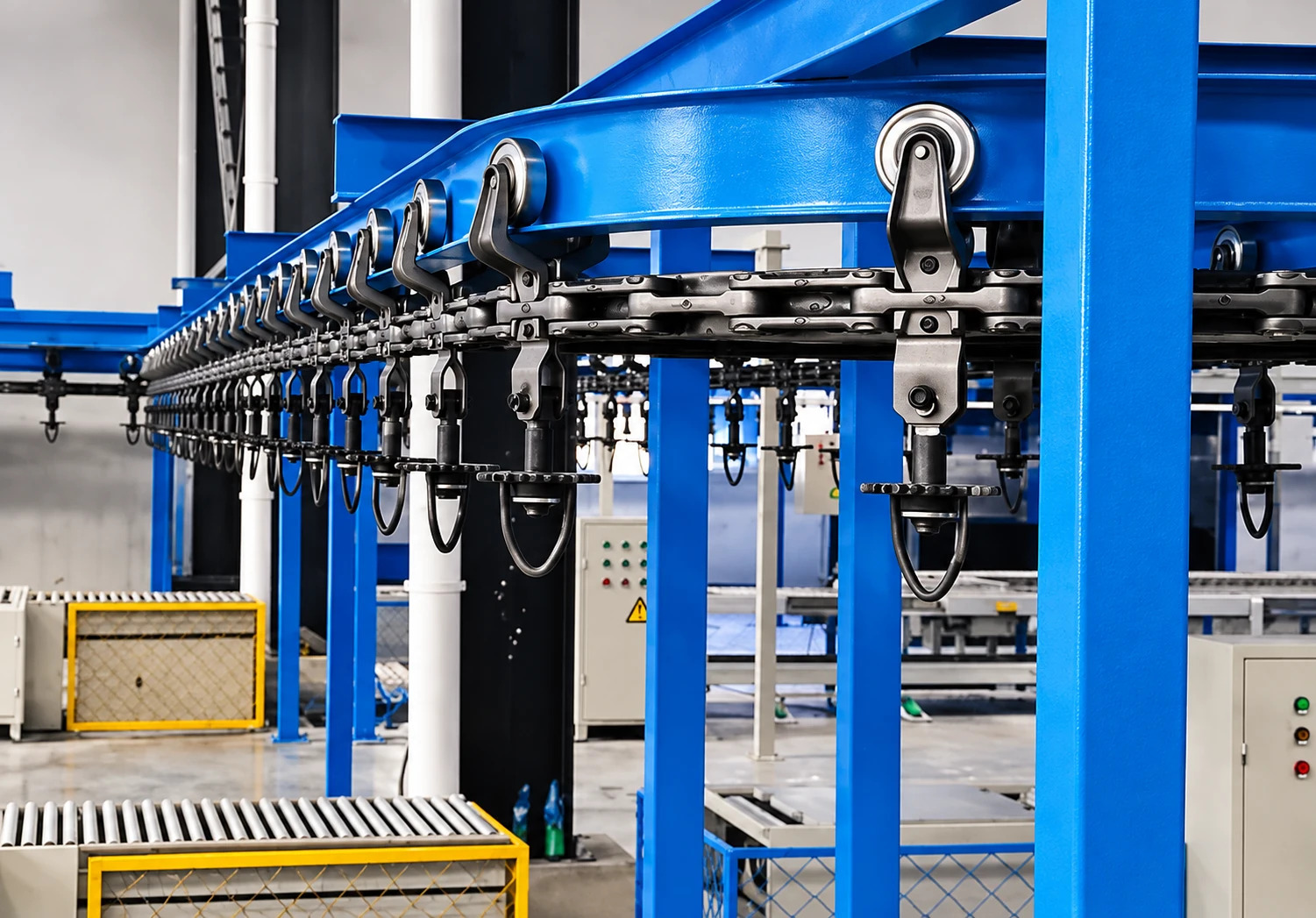
I-beam conveyors use trolleys running on an exposed beam with chain and attachments matched to the equipment. They are a useful option when the load, route and operating conditions call for a rugged conveyor with accessible running components.
Select the beam, trolley and chain together.
Chain pitch, trolley geometry, wheel profile and track section form a matched system. A beam size or chain designation on its own does not establish the capacity of an installed conveyor.
Load bars and multiple trolleys change how a carrier is supported. Their spacing also affects travel through curves and clearance between adjacent loads. Confirm compatibility before adding parts to an existing line.
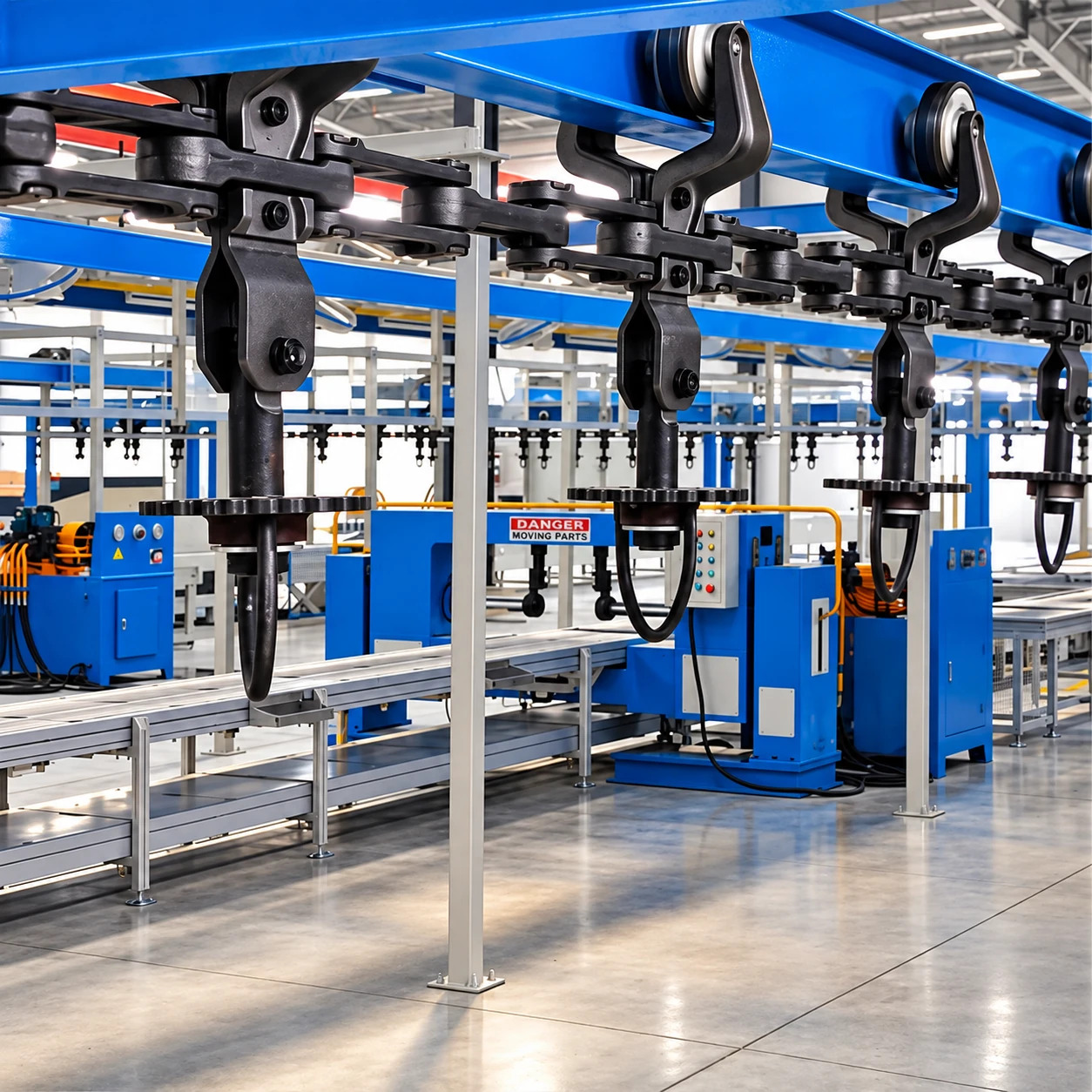
Chain conveyor component selection guide (PDF) Daifuku Automotive America · January 2024 · Sections 1, 2, 4, 5 and 7
Separate the load from the force that moves it.
Suspended load describes what the trolleys and structure carry. Chain pull describes the force needed to move the conveyor through its route. A chain-pull rating is not a payload rating.
| Factor | What to review |
|---|---|
| Operating mode | Power-only moves connected loads continuously or by indexing. Independent stops and accumulation require a different arrangement. |
| Complete carrier load | Part, fixture, attachment and load-bar weight; how the load is shared between trolleys. |
| Matched components | The chain, trolley, beam, turns and drive selected for the same equipment family. |
| Route resistance | Loaded and empty portions, turns, elevation changes and running condition affect chain pull. |
| Service environment | Accessible running parts aid inspection, while exposure and process conditions influence lubrication and maintenance. |
What Actually Sizes the Conveyor
These inputs help define the track, support steel, carrier approach, and installation plan.
| Input | Why it matters |
|---|---|
| Load weight and size | Drives track, chain family, trolley, carrier, support, and safety requirements. |
| Chain and trolley family | I-Beam conveyor systems use matched chain, trolley, and S-beam track options; capacity depends on chain size, trolley spacing, load-bar arrangement, carrier design, and route. |
| Power-only operating mode | Confirms whether the process needs continuous or indexed chain-driven movement. Independent stopping and accumulation may point toward power and free instead. |
| Drive and take-up plan | Powered I-Beam conveyor routes need review of chain pull, drive location, speed range, overload protection, take-up access, and whether one drive or a balanced multi-drive approach is required. |
| Route and clearances | Controls turns, obstructions, elevation, equipment access, and installation complexity. |
| Carrier and hook style | Affects product stability, orientation, finish protection, and operator ergonomics. |
| Support structure | Determines column layout, bracing, floor access, and future flexibility. |
| Maintenance access | Helps locate service points, lubrication areas, inspection areas, chain-stretch checks, and high-wear components. |
Keep the route serviceable and the floor useful.
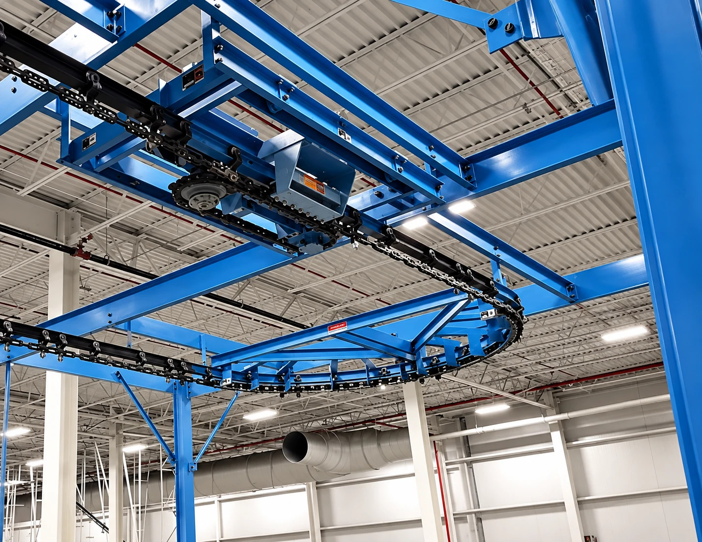
Plan the track and supports with aisles, process openings, installation access and service points. Drives, take-ups and curves need accessible space as well as structural support.
When modifying a line, review existing condition and the changed loading before deciding which components and supports can remain.
Compare the alternatives.
Enclosed track may suit a more compact arrangement. Power & free may fit independent station stops or routing. Hand-pushed monorail may fit occasional manual transfers. The operating task should determine which option is developed.
Explore the arrangements.
Look closer at the configurations that suit your production.
Bring us the bottleneck.
We’ll help plan the movement.
Share what you move, where it needs to go, and what is holding production back. A photo or rough layout is a useful start. You do not need a finished specification.
Discuss my conveyor project Work through the planning questions Complex flow or unknown rates? Explore an engineering study Or call (812) 363-1819